Repairing heating in Nissan Leaf
In the middle of the winter heating in my Nissan Leaf began to randomly stop working. I searched the internet and found that the heater often fails. The winter wasn't strong, so I reduced the use of the heater to not damage it more or blow a fuse which I read that is very hard to replace.
Repairing the PTC Heater
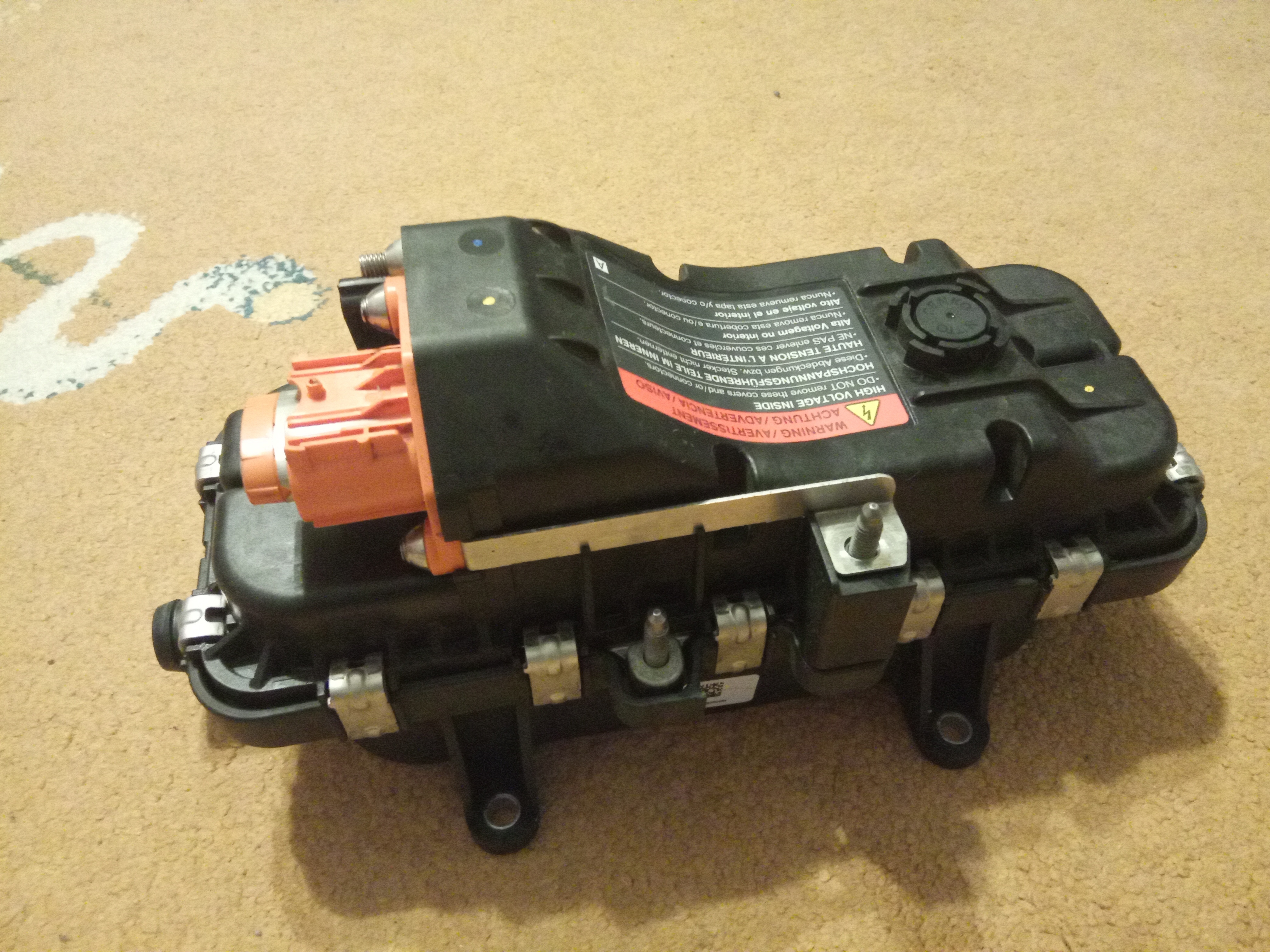
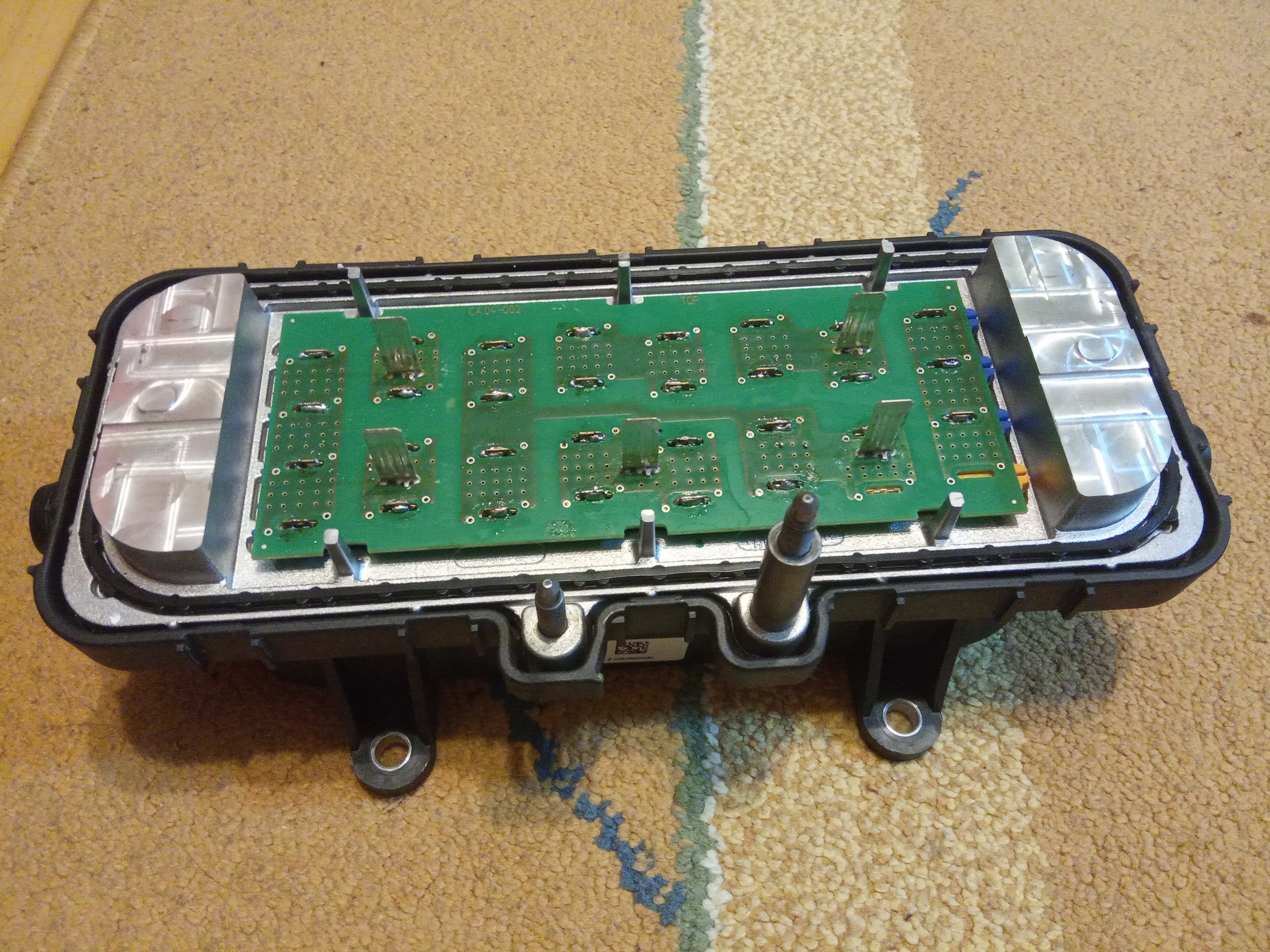
This is the heater taken from the car. If you are looking for all the steps to remove the heater from the car, they are described in the service manual. It can be easily found on the internet.
Disassembly
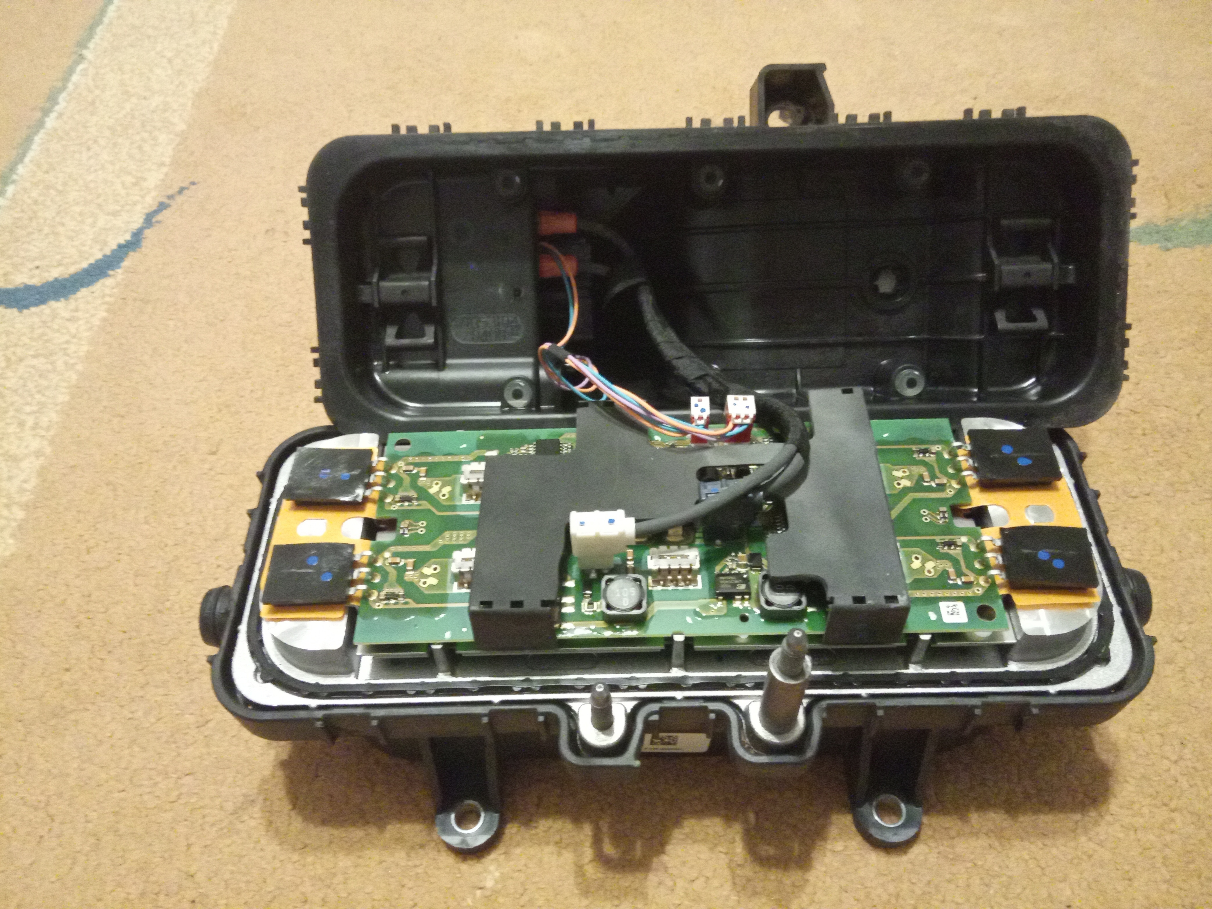
After opening the heater I found no electronic components that looked like they were damaged. This was really great information as it is very hard to find alternatives to replace them. It could be much worse if I didn't reduce the use of the heater during winter.
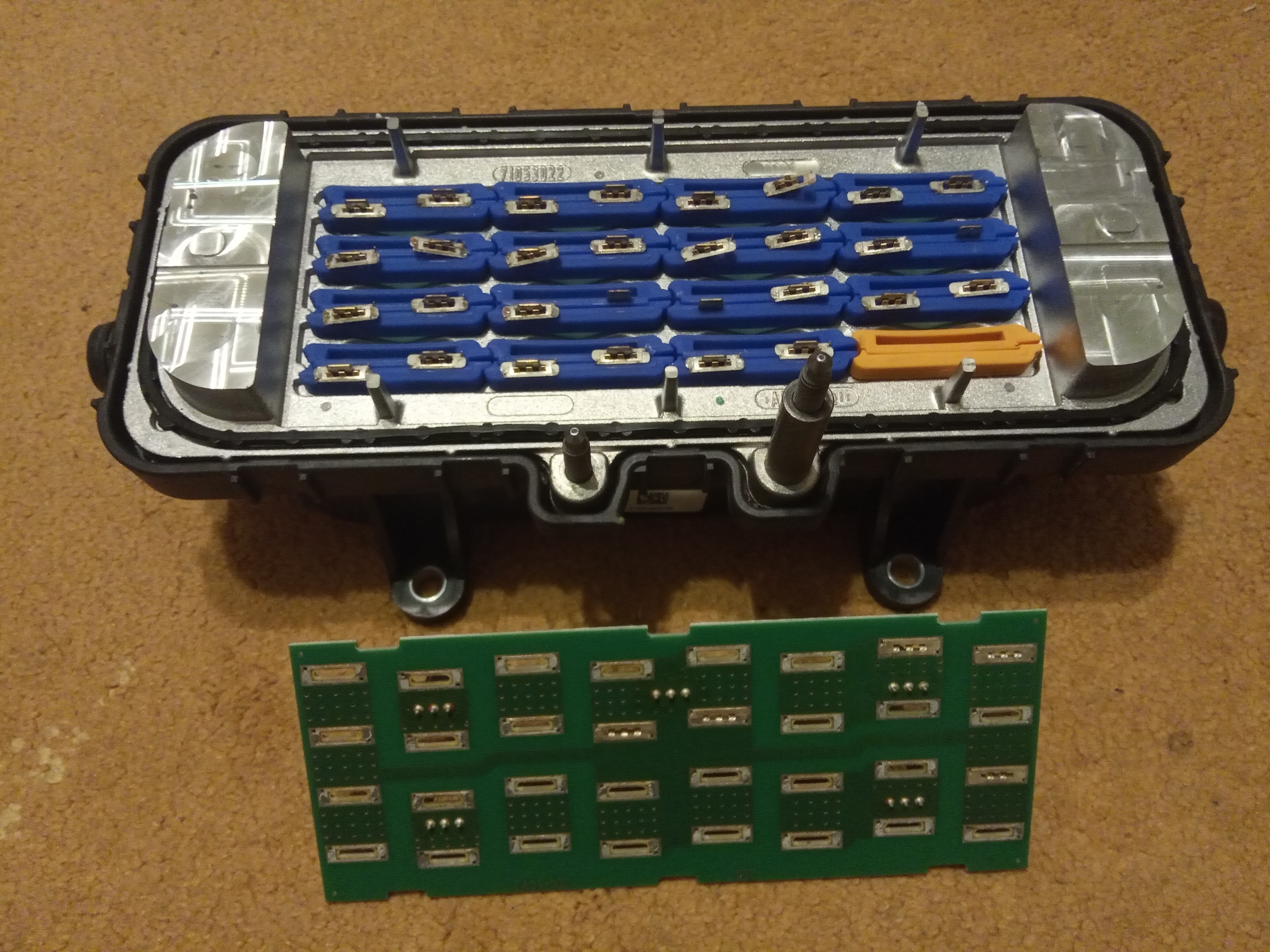
Almost all terminals stayed on the heating elements after removing the PCB, but luckily no paths were burned. Probably the loss of contact was detected early enough by the control circuit.
Soldering
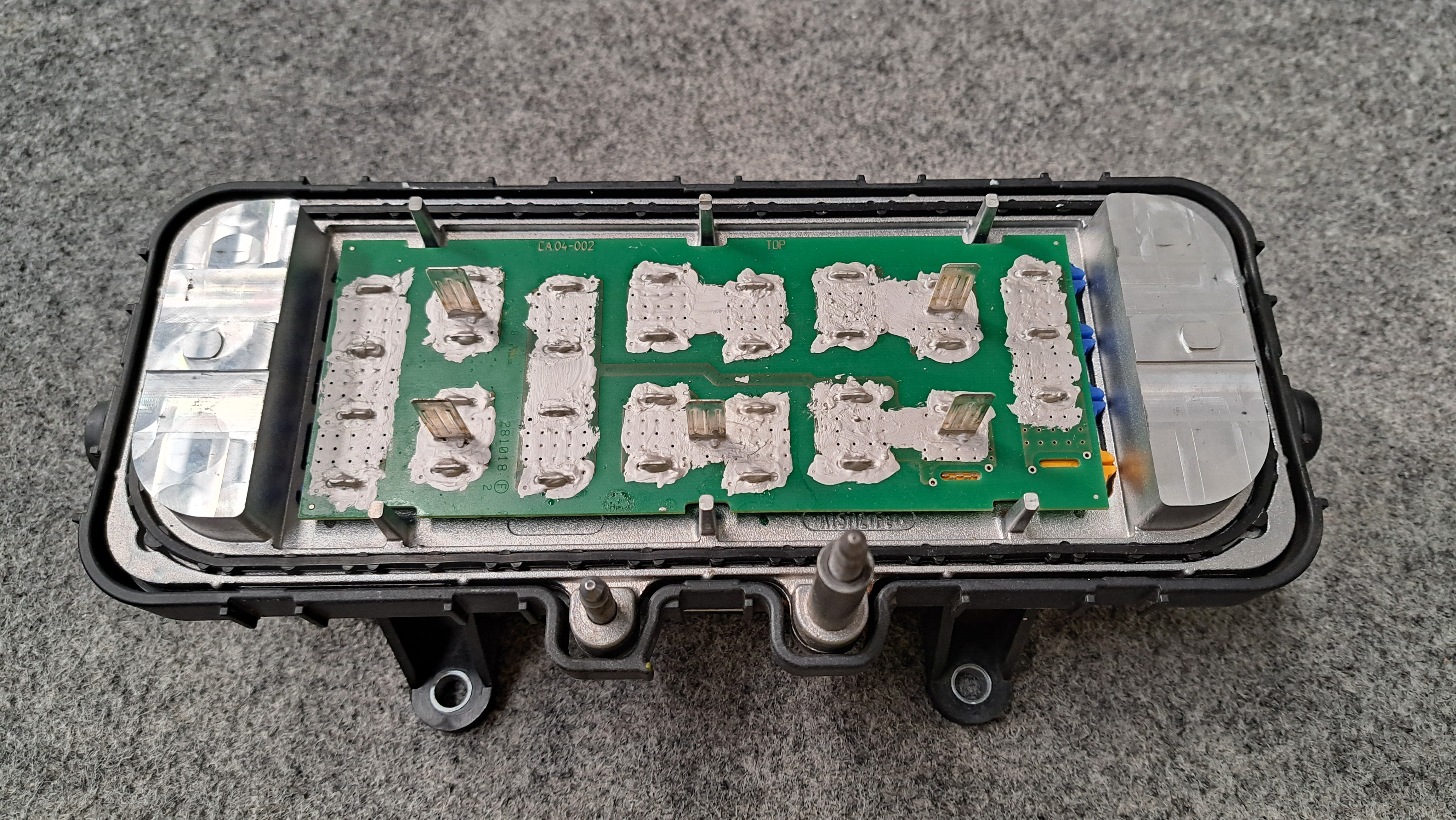
Just like the other people I decided to manually solder all terminals back to the PCB. The pads under them were not too big, so they required a lot of cleaning and scratching to make the solder stick.
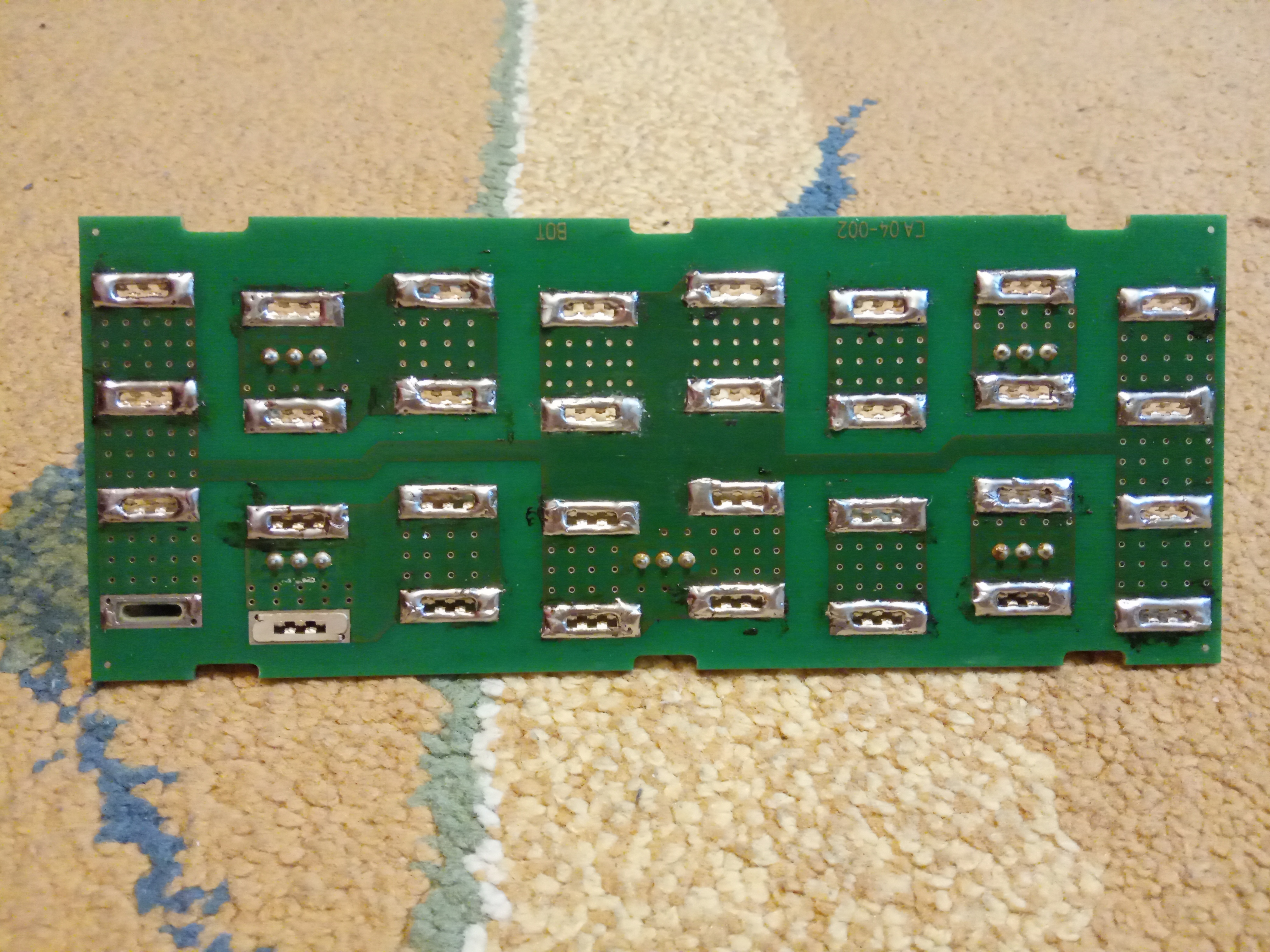
Putting the PCB back on top of the heating elements was a bit harder probably because solder on top of the terminals made them tougher.
The last concern was the contact between heating elements and terminals. I decided to solder them too. This solution make removing the PCB later impossible or very hard, but the decision was made that if it fails again the whole PCB will have to be replaced by something else.
Gluing
I also ordered an electrically conductive adhesive which was stated to be elastic. Using it I glue the heating elements to the terminals and surrounding holes in the PCB. This both increased conductivity and eliminated any contact issue between heating elements and terminals.
Limiting the PTC Heater
There are a few models of the heaters for Nissan Leaf which differ in their power. Mine is 5kW which is the most powerful available, so hopefully it has the best electronic components. The idea was to limit the maximum power, and that way make it less prone to failure in the future.
The heater communicates with the climate control unit using the LIN bus. Since I still wanted to be able to control the heater through the climate control unit, the solution here was to use a LIN bridge between them to modify the communication. I haven't found any ready to use LIN bridge, so I started working on my own.
LIN Bridge Hardware
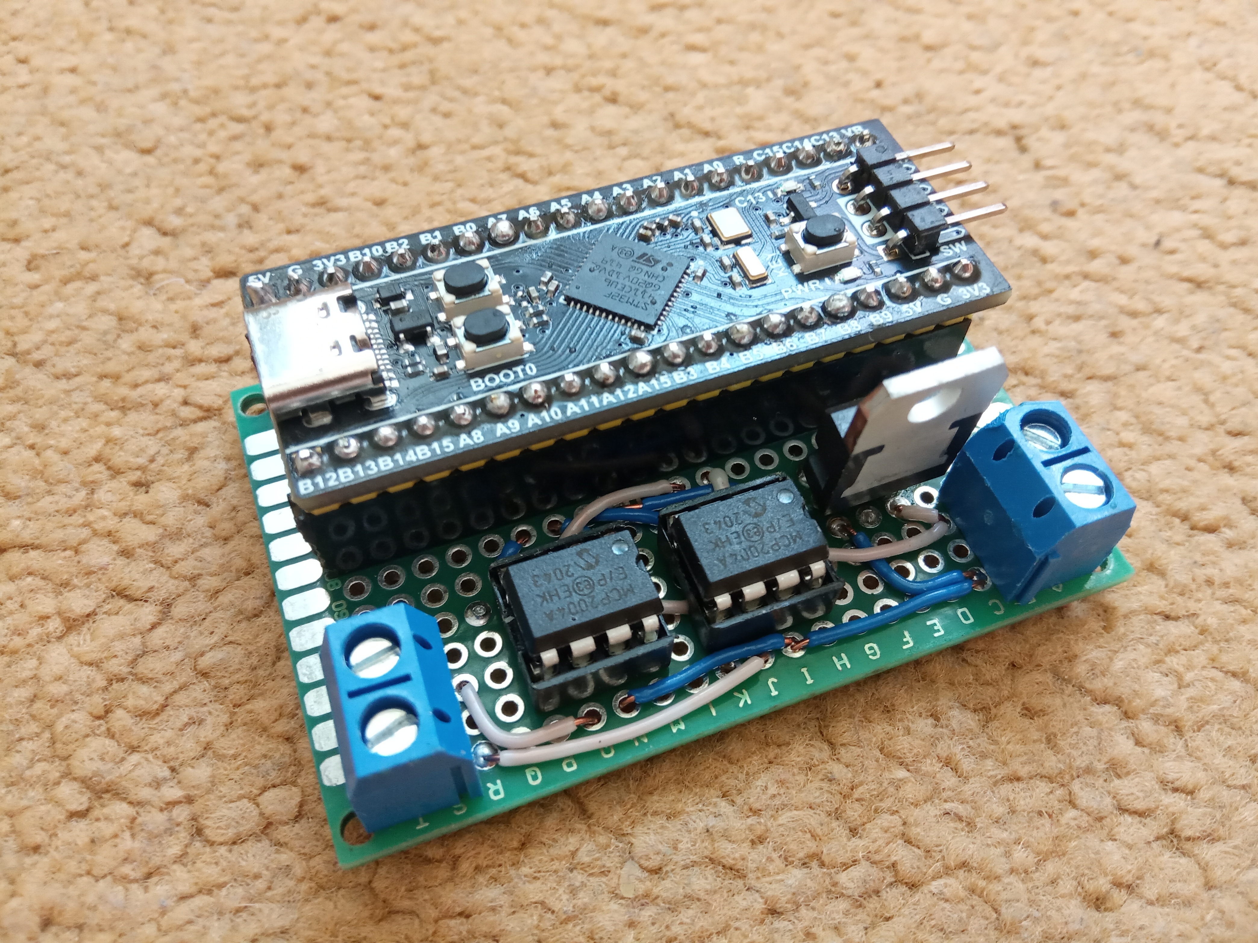
Parts that I used to build the LIN bridge:
- BlackPill v3.1 development board with STM32F411CE microcontroller. It is small and has support for two UART peripherals.
- Two MCP2004A LIN Transceiver. It is available in a DIP package which make it east to solder and potentially replace.
- LD1086V33-DG regulator. It has up to 30V input which is important factor in automotive applications.
Everything is soldered on a universal PCB. All parts except regulator are removable, which allows replacing them. There are extra pins to plug external logic analyzer and inspect the communication on the computer. They were important for me because I had to analyze and understand the protocol between the climate control unit and the heater to write software to limit the power.
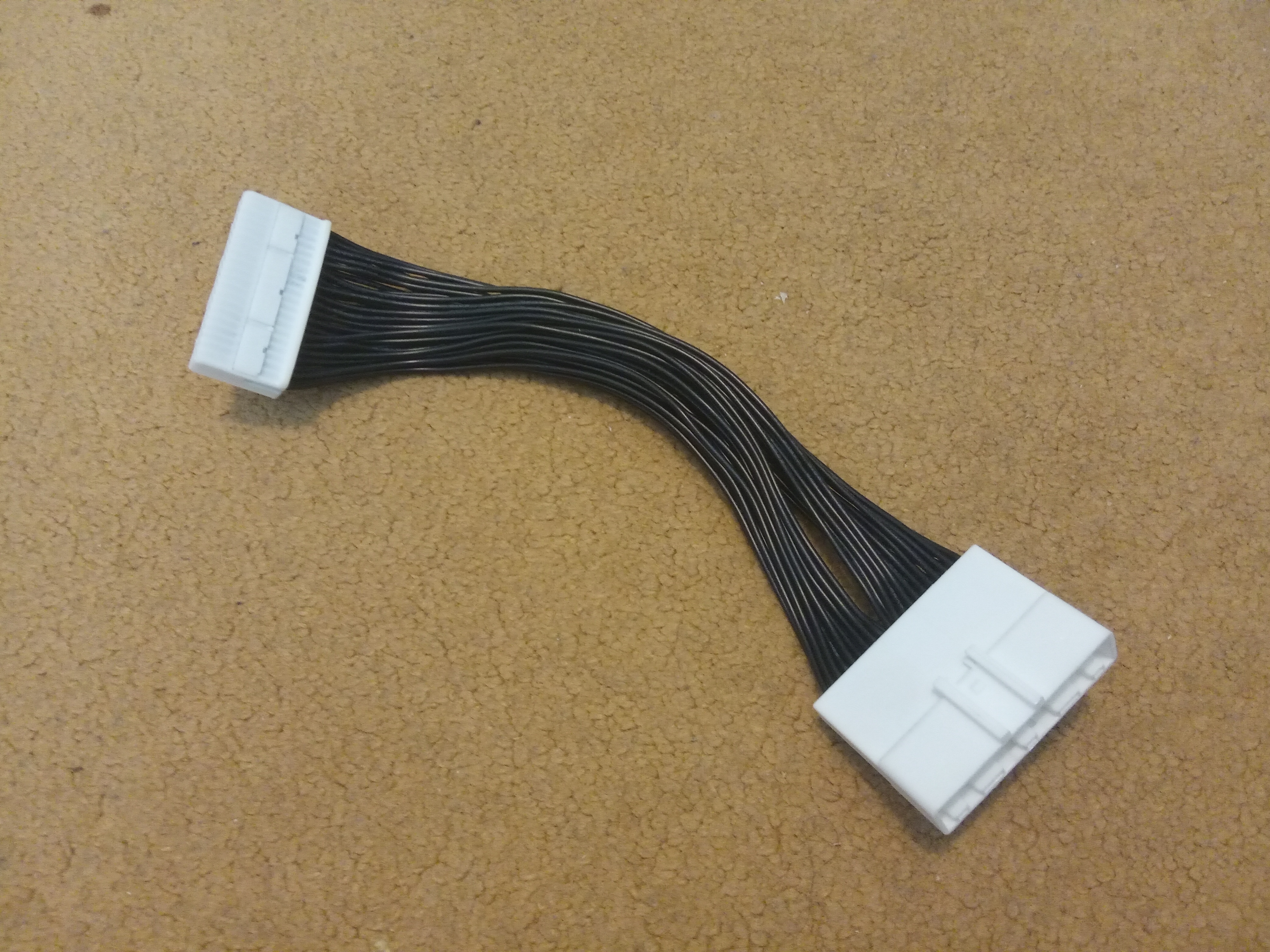
The LIB bridge was put behind climate control unit as there is a lot of space. I also found and ordered an extension cable to inject the LIN bridge on it, instead of cutting original climate control unit cables.
Communication Analysis
After the hardware was ready, I began inspecting the communication between the climate control unit and the heater using logic analyzer.
The climate control unit which is a LIN master transmits two frames with IDs 0x59 and 0x24 every 100ms. The second one is offset by 40ms.
The frame with ID 0x59 is and Sporadic Frame, the master sends the header and the response. 

The first frame was transmitted when the heater was disabled and the seconds when was enabled. The only difference is on the third data byte which represents the target power.
The frame with ID 0x24 is an Unconditional Frame. The master only sends the header and expects response from the slave. 
This frame probably is used to report status and errors of the heater, but it is not important for this project.
LIN Bridge Software
I started with a simple program to forward all LIN headers and responses through the bridge without any data modification. However, it didn't fully work. The problem was caused by Unconditional Frame because when master transmits a header it expects to get response within a certain amount of time called response space. My program was forwarding the header from the master to the slave, then waiting for the response from slave, which eventually was forwarded to the master. The time needed to receive response and transmit it was longer than response space, so the master discarded that response. This made my realize that LIN bridges are quite problematic and probably why they are not very popular.
By using the fact the climate control unit transmits frames very often I was able to work around that problem. Instead of waiting for the response from slave to forward it, the bridge stores previous responses by PID as they arrive. When the master transmits Unconditional Frame the bridge immediately transmits response to the master if it was previously received from the slave and stored by the matching PID. Now the simple forwarding program was working correctly, and the climate control unit was able to communicate with the heater.
The last step was to modify the third date byte in the Sporadic Frame with ID 0x59 from the master. I implemented it without any further problems and after testing it, everything worked as expected. The heater power was successfully limited even in window defrosting mode.
Result
After repairing the heater has worked with no issue throughout the next winter. Even with the limited power it was enough to defrost the windshield fast.