eBike Display Reprogramming
The KT LCD8H display in my opinion as a device is looks nice. However, when it comes to its graphic design, I really didn't like it. Furthermore for my use case most of the information displayed on the screen wasn't needed.
Research
I have searched on the internet to check if anyone has done this before. I haven't found anything else other that some pictures of the disassembled display. Nevertheless they were actually helpful because I could see some of the hardware before disassembling it myself. This was quite important as these displays aren't cheap, so with these pictures I was able to decide if it is even viable to continue.
The microcontroller was STM32F103RCT6 and the LCD was JJY3477 with a ILI9488 driver. I decided that this is a good candidate for reprogramming as I'm experienced with STM32 microcontrollers and have used similar LCD drivers.
Reverse Engineering
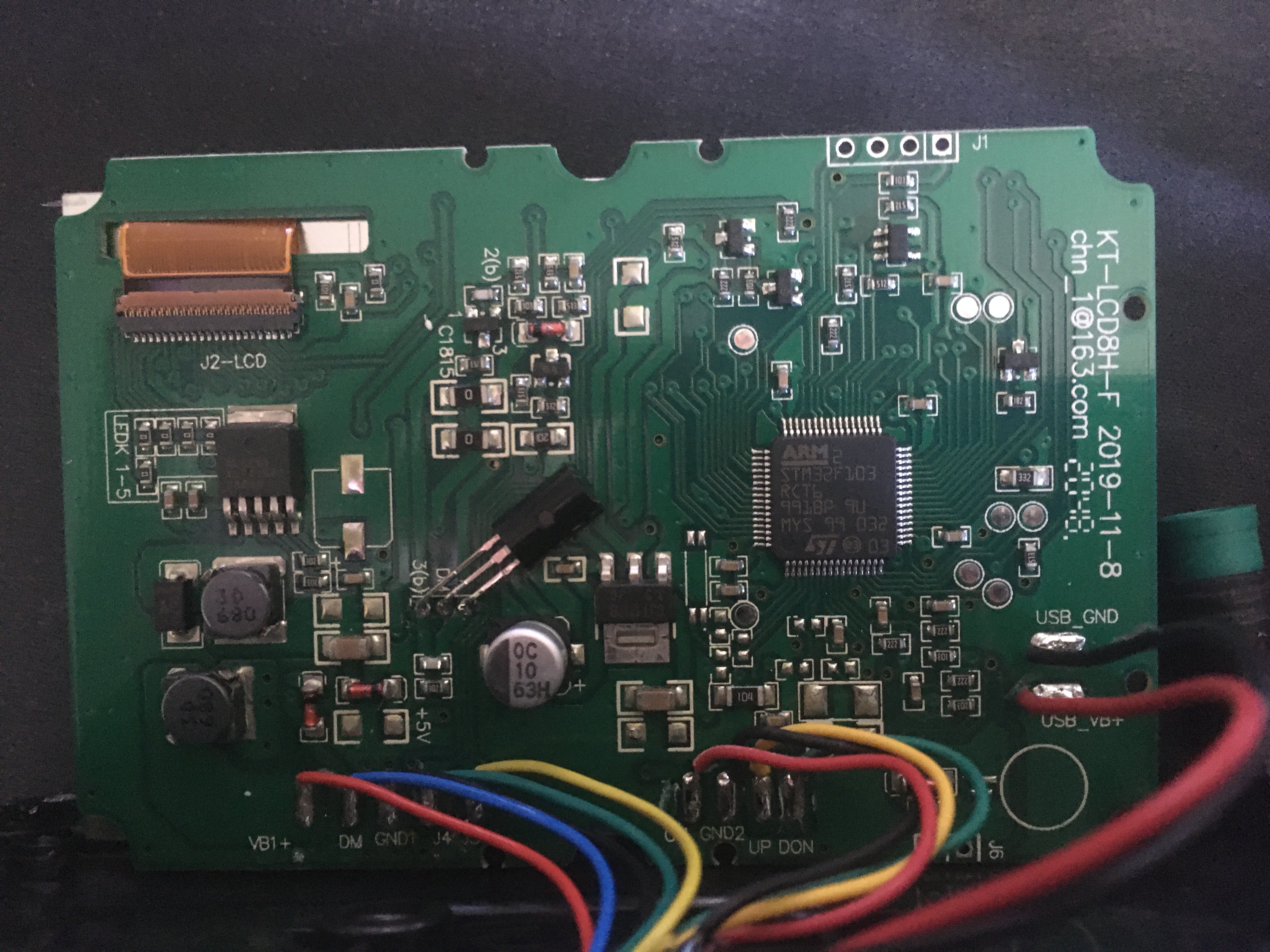
After I disassembled the display and it was slightly different from what I found online, but the microcontroller and LCD were still the same. I began analyzing connections between the microcontroller and rest of the hardware. By tracing paths on the circuit board, I was able to determined which pins were connected to buttons and socket of the display. There was also a voltage divider based battery voltage measurement circuit and some other less important circuitry.
Reverse engineering the LCD was more challenging. Although I could identify connections between the microcontroller and LCD, I didn't know their function. However, in one of the online stores selling that LCD, I found a scan of the documentation page that listed the names of each pin on the flexible flat cable. With this information, I could fully understand the hardware of the display.
New Design
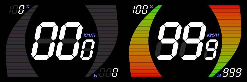
My dream design was to have big digits for speed in the middle and two bars on the left and the right side for battery level and motor power respectively. Since I'm have very little graphic skills, I decided to render it procedurally using code. For each graphic element I wrote a function that takes pixel coordinates and returns a color. After spending some time tweaking the math behind these functions I ended up with a design that I'm really proud of.
Firmware
Writing new firmware wasn't that simply. The difficulty wasn't in the LCD driver nor communication, but in the implementation to display my custom graphic design. Main constraints were limited flash size of the microcontroller which is 256 kB and the fact that the bounding boxes of the graphic elements overlap. Due to the lack of double buffering in the LCD driver, simply storing and drawing each graphic element as a rectangle image wouldn't work because they would cover other graphic elements. Another reason is that they would simply not fit in the flash, so I had to apply some tricks in order to implement this design.
For gauges I decided to store them by rows, but also slice each row to only included pixel which were inside the gauge shape. Pixels of all slices were then stored in an continuous array. To be able to reconstruct the gauge I also had to store additional information about the slice for each row. That data included the index of the first pixel in the continuous array, number of pixels in a slice and the offset since each slice can start at different position within its row. This way I not only saved flash space, but also avoided the issue of drawing over other graphic elements.

Digits also required special handling because adjacent segments slightly overlap. After some thinking I found that splitting them horizontally into two halves is a solution. It allows drawing without overlapping and saves some flash space as the second half can be recreated by flipping the first half. By merging halves the total number of images is reduced as some of the non flipped ones are the same as flipped ones.

All other small elements were stored as an continuous array of all pixels in their bounding boxes along with width and height information. They didn't require much flash space, so there was not reason to store them in a more advanced way.
Result
After reverse engineering the hardware and writing the new firmware for it, the reprogrammed display is ready to be used.